.png)

Zynq-7000 + AXI Slave with Interrupt Hello World on a ZC702
- Zach Pfeffer
- May 7, 2019
- 5 min read
Updated: May 14, 2023

This post lists step-by-step instructions for creating an AXI slave with an interrupt using Vivado HLS, integrating the slave into a Zynq-7000 system using Vivado, writing a driver that exercises the AXI slave and responds to the interrupt and running everything on a ZC702.
Versions Used
Xilinx Vivado 2018.2 & SDK 2018.2
Xilinx Vivado HLS 2018.2
ZC702 Rev 1.1
Windows 7 SP1
Before you Start
Review the ZC702 JTAG and serial port set up instructions @ [link]. These instructions are also reviewed below.
Contents
Part 1: Create an AXI Slave with an Interrupt Using Vivado HLS
Part 2: Create the Vivado Project
Part 3: Add the axi_lite Repo to the UP Catalog
Part 4: Create the Zynq-7000 in IP Integrator
Part 5: Connect the HLS Interrupt Line to Zynq
Part 6: Create a Top-Level HDL Wrapper
Part 7: Synthesize and Generate the Bitstream
Part 8: Export the Design and Open the SDK
Part 9: Install the USB-to-UART Driver and Get the COM Assignment
Part 10: Create the Test App and BSP
Part 11: Test Debug Run + Further Config
Part 12: Test the AXI Module and the Interrupt
Part 1: Create an AXI Slave with an Interrupt Using Vivado HLS
Step 1: Start Vivado HLS 2018.2
A. Click Windows
B. Click Xilinx Design Tools
C. Click Vivado 2018.2
D. Click Vivadi HLS 2018.2

Step 2: Click Open Example Project

Step 3:
A. Expand Design Examples
B. Click axi_lite
C. Click Next

Step 4:
A. Set Location to C:\vivadoprjs\axislaveint
B. Click Finish

You should see:

Step 5: Click Run C Synthesis

After a little bit (1 min on my T460 [link]) you should see Finished C synthesis. in the Console

Step 6: Click Export RTL

Step 7:
A. Click the Vivado synthesis, place and route checkbox
B. Click OK

After a little bit (3 min on my T460) you should see Finished export RTL. in the Console

Step 8: Close Vivado HLS
A. Click File
B. Click Exit

Part 2: Create the Vivado Project
Step 1: Start Vivado

Step 2: Click Create Project

Step 3: Click Next

Step 4:
A. Set Project name to zynqsys
B: Set Project location to C:/vivadoprjs/axislaveint (created above)
C. Click the Create project subdirectory checkbox
D. Click Next

Step 5:
A. Select RTL Project
B. Check the Do not specify sources at this time check box
C. Click Next

Step 6:
A. Click Boards
B. Type ZC702
C. Click on the ZYNQ-7 ZC702 Evaluation Board box
D. Click Next

Step 7: Click Finish

You should see:

Part 3: Add the axi_lite Repo to the UP Catalog
Step 1: Click IP Catalog

Step 2:
A. Right-click on Vivado Repository
B. Click Add Repository...

Step 3:
A. Expand the directory tree and click on C:\vivadoprjs\axislaveint\axi_lite\proj_axi_lite\solution1\impl\ip
B. Click Select

C. Click OK

You should see Example under User Repository / VIVADO HLS IP:

Part 4: Create the Zynq-7000 in IP Integrator
Step 1: Click Create Block Design

Step 2: Use defaults, click OK

Step 3: Click +

Step 4:
A. Type Zynq
B. Double-click on ZYNQ7 Processing System

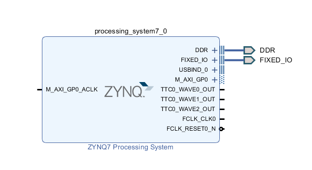
Step 5: Click Run Block Automation

Step 6: Use defaults, click OK

You should see:
Part 4: Connect the AXI Slave with Interrupt from HLS to Zynq-7000
Step 1: Click +
Step 2:
A. Type Example
B. Double-click on Example

Your screen should look similar to:

Step 3: Click Run Connection Automation

Step 4: Use defaults, click OK

Your screen should look something like:

Part 5: Connect the HLS Interrupt Line to Zynq
Step 1: Double click the ZYNQ block

Step 2: Enable IRQ_F2P[15:0]
A. Click Interrupts
B. Check the Fabric Interrupts checkbox
C. Expand the Fabric Interrupts drop-down
D. Expand the PL-PS Interrupt Ports
E. Check the IRQ_F2P[15:0] checkbox
F. Click OK

You should then see the IRQ_F2P[0:0] port on Zynq:

Step 3: Connect IRQ_F2P[0:0] to example_0 interrupt
A. Click and hold mouse button on IRQ_F2P[0:0]
B: Drag and release mouse button on interrupt

You should see:

Part 6: Create a Top-Level HDL Wrapper
A. Click Sources
B. Right-click design_1 (design_1.bd) (1)
C. Click Create HDL Wrapper...

D. Leave Let Vivado manage wrapper and auto-update, click OK

After a little time you should see:

Part 7: Synthesize and Generate the Bitstream
Step 1: Click Run Synthesis

Step 2: Use defaults, click OK

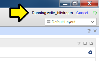
You'll see the status in the upper right corner.
A sample of the output:

Step 3:
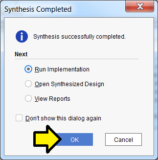
Wait approximately 1 to 5 min until you see Synthesis Complete in the upper right corner...

...and click OK to Run Implementation:
Step 4: Use defaults, click OK

Again, you'll see status in the upper right:

Step 5:
Wait approximately 1 to 5 min until you see Implementation Complete in the upper right corner...

A. Select Generate Bitstream
B. Click OK

Step 6: Use defaults, click OK
Again, you should see the status in the upper right:
Step 7: Click Cancel

You may see this window pop-up:

Feel free to send feedback, set a reminder or click No. If you click No you may see:

...click OK to dismiss.
Part 8: Export the Design and Open the SDK
Step 1:
A. Click File
B. Click Export
C. Click Export Hardware...

Step 2:
A. Click the Include bitstream checkbox
B. Click OK

Step 3:
A. Click File
B. Click Launch SDK

Note: you can open the workspace directly from the SDK by opening the SDK and specifying C:\vivadoprjs\axislaveint\zynqsys\zynqsys.sdk as the workspace.
Step 4: Use defaults, click OK

You should see:

Note the Base Address of example_0:
A. Scroll down
B. Look for example_0

Part 9: Install the USB-to-UART Driver and Get the COM Assignment
Steps:
A. Goto [link] for the Silicon Labs CP210x USB to UART Bridge VCP Drivers
B. Download and unzip the correct installer for your OS
C. Install the driver (I did not need to restart on Windows 7 SP1)
D. Click Windows
E. Click Devices and Printers

F. You should see Silicon Labs CP210x USB to UART BridgeG.
G. Note the COM port # (you'll need this later)

Part 8: Configure the Board to Boot from JTAG, Connect it to the PC and Power it On
Step 1: Set SW16 to JTAG mode [mode documentation see p.16]

For the rest of the jumpers see the high-resolution photo of the board in the correct state at [link]. Step 2: Connect a Micro-B to Type-A (host connection) USB cable from U23 (Diglent USB JTAG interface) to the host PC
U23:

Micro-B connector:

Type-A connector:

Step 3: Connect a Mini-B to Type-A (host connection) USB cable from J17 (CP2103GM USB-to_UART Bridge) to the host PC.
J17:

Mini-B connector:

Type-A connector:

Step 4: Turn on the board

Part 10: Create the Test App and BSP
Step 1:
A. Click File
B. Click New
C. Click Application Project

Step 2:
A. Type testaxislaveint into Project name:
B. Ensure the Board Support Package: Create New radio button is clicked and the name given is testaxislaveint_bsp
C. Click Next

Step 3:
A. Click Hello World
B. Click Finish

You should see:

Part 11: Test Debug Run + Further Config
These instructions allow debug to be set up more easily than entering in the details manually. After running a debug session, the Debug Configuration is fixed up to reset the FPGA and program the bitstream. The debugger COM port is also configured so that output can be read and the steps to test it and see Hello World are listed.
Step 1:
A. Right-click testaxislaveint
B. Click Debug As
C. Click Launch on Hardware (System Debugger)

Step 2: Click OK (if you see this)

If you see this message click Yes. We'll handle this in the next part.

...click Yes.

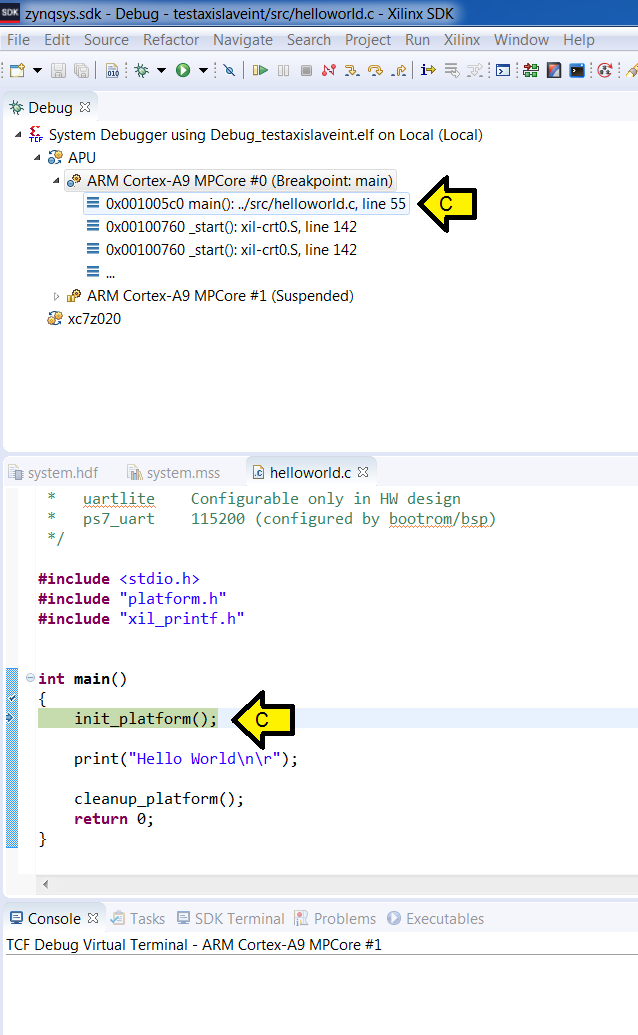
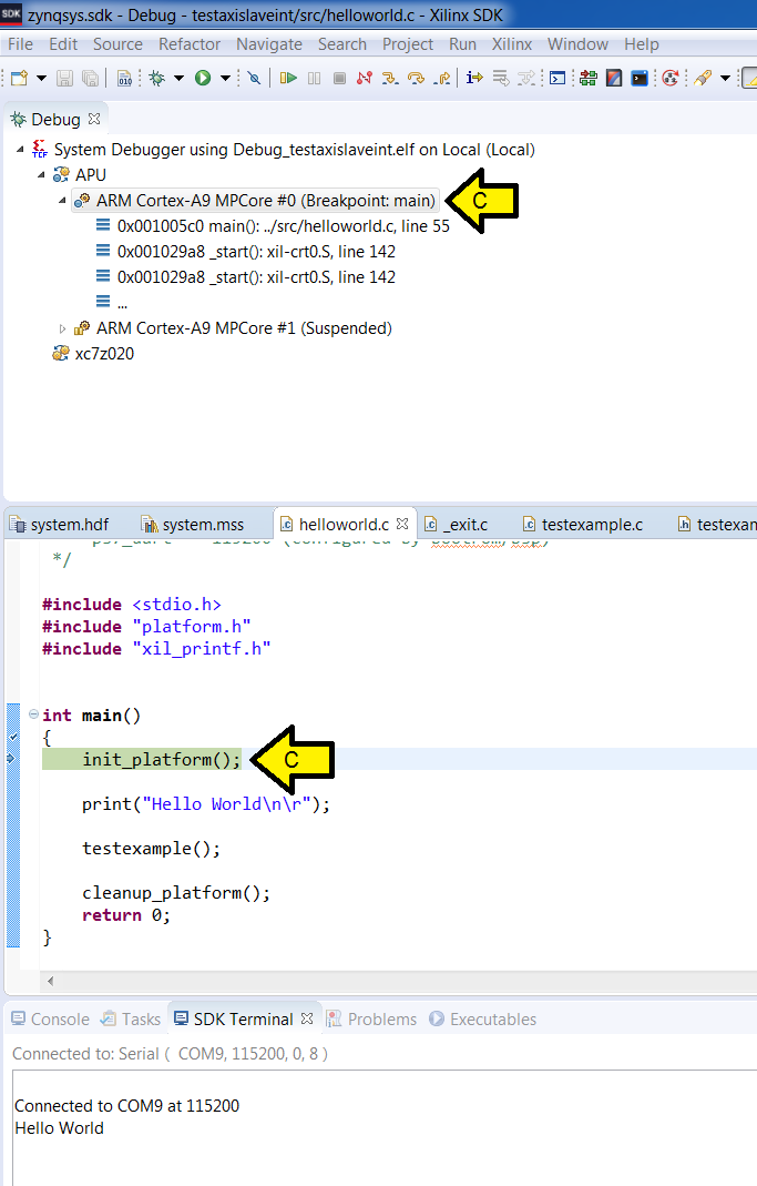
You should see the Debug Perspective display the code broken on init_platform():
A. Debug context on main()
B. helloworld.c on init_platform()

Step 3:
A. Click Run
B. Click Debug Configurations...

Step 4:
A. Ensure System Debugger using Debug_testaxislave on Local is selected (it should be)
B. Click the Reset entire system checkbox
C. Click the Program FPGA checkbox
D. Click Apply
E. Click Close

Step 5: Configure Debug View COM
A. Click SDK Terminal
B. Click the '+' (Connect to serial port.)

Step 6: Set Debug View COM settings
A. Enter the COM# from above
B. Click OK

Step 7: Make sure you see Hello World on the console
A. Click on the bug

B. Click OK

C. Wait for the system to hit the breakpoint on main()
D. Click Resume

E. Wait until you see exit():
F. Click on SDK Terminal
G. Observe Hello World

Part 12: Test the AXI Module and the Interrupt
Step 1: Click on the C/C++ view

Step 2:
A. Expand testaxislaveint
B. Expand src

Step 3:
A. Right-click on src
B. Hover over New
C. Click File

D. Type testexample.c
E. Click Finish

F. Copy and paste the following code into testexample.c
Step 6:
A. Right-click on src
B. Hover over New
C. Click File
Step 7:
A. Type testexample.h
B. Click Finish
Step 8: Copy and paste the following code into testexample.h
Step 9: Update helloworld.c
A. Double-click helloworld.c

B. Insert testexample(); after print("Hello World\n\r"); and #include "test example.h" after #include "xil_printf.h"

C. Click save-all

Step 10: Run it
A. Click on the bug

If you see WARNING pop-up this click OK

B. Click Yes to confirm the switch to the Debug perspective

C. You should see execution stopped at main(
D. Click Resume

E. You should see all of the tests passing

References
2018.2 UG871 High-Level Synthesis (code at p.240-243) [link]
Free Online HTML Escape / Unescape @ [link]
Xilinx logo found via https://twitter.com/xilinxinc at [link]